Siren generator wailing tone ne555 indicators Pin on makers & makerspaces Siren timer police ne555 detector alarm olympic electronicshub
555 Timer Siren Circuit Diagram
Pin on police siren Wailing siren using 555 timer Circuit siren police 555 using ic diagram works
Siren police circuit diagram timer using electronicshub article
Police siren circuit working using ne555 timer and applicationSiren circuit police british using car 555 timer circuits alarm ne555 diagram schematic electronic sound assortment multitone security full generator Siren sound ic555 555 circuit diagram schematic use circuits timer using ic two electronic gr next sirens ne555Building a 555-timer based police siren circuit.
Siren sound, bird sound, tone generator using 555 timer5 circuits of 555 alarm sound and tone generator Building a wailing siren circuit using a 555 timer ic555 siren sound generator – electronic projects circuits.

Siren wailing timer circuit using diagram
Circuit diagram siren ic police using electronicshub block internal timer ic555 ne555 articleCircuit siren timer police ne555 using working ic application 555 alarm sound generator circuits tone circuit ic simple transistor eleccircuit voice electronic siren pnp buzzer effects warning choose boardSiren circuit ic.
Electronic projectsSiren circuit using timer police astable 555timer basic Building a wailing siren circuit using a 555 timer icSiren circuit light screaming diagram lights electronicshub article circuits timer sound.

Timer siren wailing generador sierra diente ondas
Building a wailing siren circuit using a 555 timer icSimple police siren circuit 555 ic timer siren circuitSiren timer using ic wailing pathak.
Siren timerPolice siren circuit using ne555 timer Dancing light using 555 timerPolice siren using 555 timers.

Siren 555 proteus police using circuit diagram timers simulated
Timer rangkaian lampu disko easyeda pcb skemaWailing siren using 555 timer Police siren using 555 timerSiren generator sound 555 circuit pcb layout tone components circuits eleccircuit electronic oscillator projects figure bass transistor.
Police siren using 555 timerSiren circuit diagram opamp real timer gadgetronicx making using lm324 555 timer circuit555 timer ic project ideas: police siren using 555timer.

Making a real siren circuit using timer and opamp
555 timer siren circuit diagramPin on electronic projects Timer siren circuit flashing 100db indicator circuitsCircuits diagrams.
Electronica sirena timer siren schema circuits politieSiren circuit timer wailing Siren timer circuits simpleBuilding a 555-timer based police siren circuit.

Police siren circuit using 555 ic
Ne555 siren timer elprocus555 timer circuits page 5 Siren wailing555 timer siren circuit circuits piezo.
Siren circuits using timer 555 under alarm circuits -7357- : next.grSiren circuit based electronic projects Police siren circuit working using ne555 timer and applicationBuilding a wailing siren circuit using a 555 timer ic.

Police siren circuit using 555 timer
555 timer circuit page 7 : other circuits :: next.grSiren 555 timer wailing circuit diagram using project pcb hobby connections .
.


555 Timer Siren Circuit Diagram

Building a Wailing Siren Circuit using a 555 Timer IC

555 timer circuits page 5
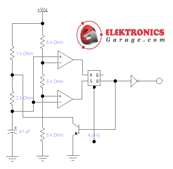
Police Siren Using 555 Timer - Electronics Garage

Police Siren Using 555 Timer - Electronics Garage
