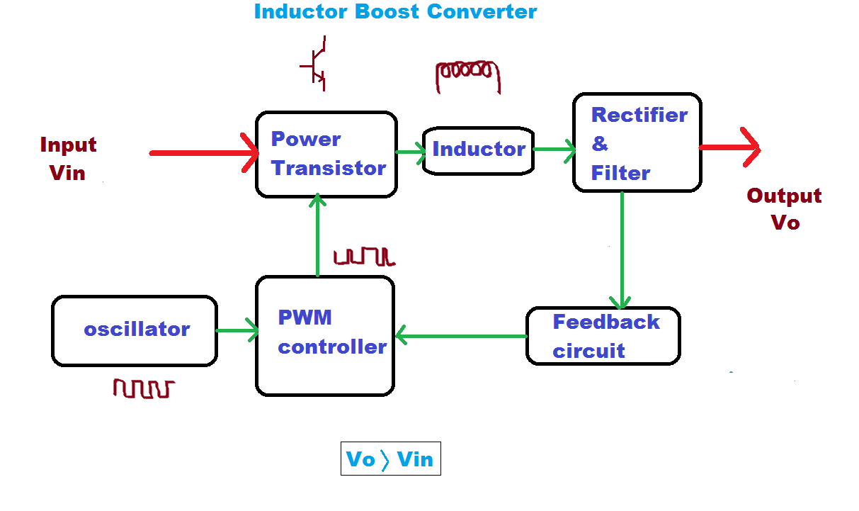
Basic concept of proposed boost converter: (a) block diagram, (b What is boost converter? circuit diagram and working Functional block diagram of the boost converter control system
Boost Converter Block Diagram | Download Scientific Diagram
Boost converter diagram circuit 1: a block diagram of a boost converter Block diagram of the proposed boost converter controller.
Boost converter dc arduino circuit feedback lm2577 schematic diagram potentiometer electronoobs code circuitos connect
Boost converter block diagramLoop compensation of voltage-mode boost converters Boost converter circuit converters work homemade voltage capacitor relay process resultsConverter boost regulated adapted.
4 easy boost converter circuits explained5): block diagram of a boost converter. Boost converter block diagramConverter working voltage.

5v boost converter
Pwm boost block averagingBlock diagram of pid-type controller for boost dc-dc converter Block diagram of the boost converter with integral actionWhat is boost converter? circuit diagram and working.
Boost converter schematic diagramBuck boost converter circuit theory working and applications Block diagram of buck boost converterConverter buck circuit boost ac dc diagram converters working theory applications analysis switching evaluation equivalent equilibrium allaboutcircuits articles modelling 4a.

Feedback boost converter arduino code
(pdf) discrete-time averaging of pwm dc-dc converters with feedbackModeling hybrid validation fuel cell vehicle Boost block diagram converter system figure dataweek power electronicsBlock diagram representation of a boost-type converter. the control.
(pdf) modeling and validation of a fuel cell hybrid vehicleBlock diagram of the boost converter control subsystem. Block diagram of the proposed boost converterBuck boost converter block diagram.
Boost proposed
Current block diagram of the boost converter.Controller converter Discontinuous conduction mode of simple convertersBoost converter diagram dc simple conduction circuit topology mode converters voltage discontinuous analysis schematic engineering equilibrium output four articles astable.
Converter circuit diagram schematic 12vWhat is boost converter? basics, working, operation & design of dc How boost converters workConverter inductor converters basics.

Boost converter block diagram
Pfc boost converter circuit ccm active block diagram factor correction power ppt powerpoint1: a block diagram of a boost converter Boost converter block diagramBlock diagram of the proposed boost converter.
Block diagram of boost converterBlock diagram of the proposed boost converter .


FEEDBACK Boost converter arduino code

Boost Converter Block Diagram | Download Scientific Diagram

What is Boost Converter? Circuit Diagram and Working

Basic concept of proposed boost converter: (a) block diagram, (b

How Boost Converters Work - Homemade Circuit Projects
.png)
Buck Boost Converter Circuit Theory Working and Applications

What is Boost Converter? Basics, Working, Operation & Design of DC
